This is the third post in our series from our Thermoforming Handbook, a guide that, until now, was only available to our customers and partners. We’re releasing the whole thing in a series of posts right here on our blog.
We’ve previously released:
If you’re someone who uses custom plastic manufacturing professionally and you’re interested in getting your own copy, just send us a message and we’ll be happy to send you one. As always, these are general guidelines. Any project or design needs to be reviewed by a qualified thermoforming professional before it goes into production, and the sooner you get one of those qualified professionals involved in the process, the smoother things tend to go. If you’re looking for a qualified professional, we know a few who would be happy to help.
Tooling is simply the industry term for creating the mold used in thermoforming. Unlike injection molding, thermoforming uses a single-sided mold (male or female), resulting in significant cost savings.
Temperature-Controlled, Aluminum Tooling Is the Best Choice You Can Make
Thermoforming can use several different types of prototype tooling, including wood or RenShape tooling. At Ray Products, we use exclusively aluminum, temperature-controlled tooling for production quantities, and only consider other materials for non-production or bridge tooling.
Key Advantages of Liquid-Cooled Aluminum Tooling
- Allows for more precise, repeatable results than any other material.
- Liquid cooling allows for faster and more consistent production time.
- Allows for running engineered resins and materials with a very tight processing window.
The good news is that even high-grade, liquid-cooled aluminum tooling is far more cost effective to produce than injection molding tooling.
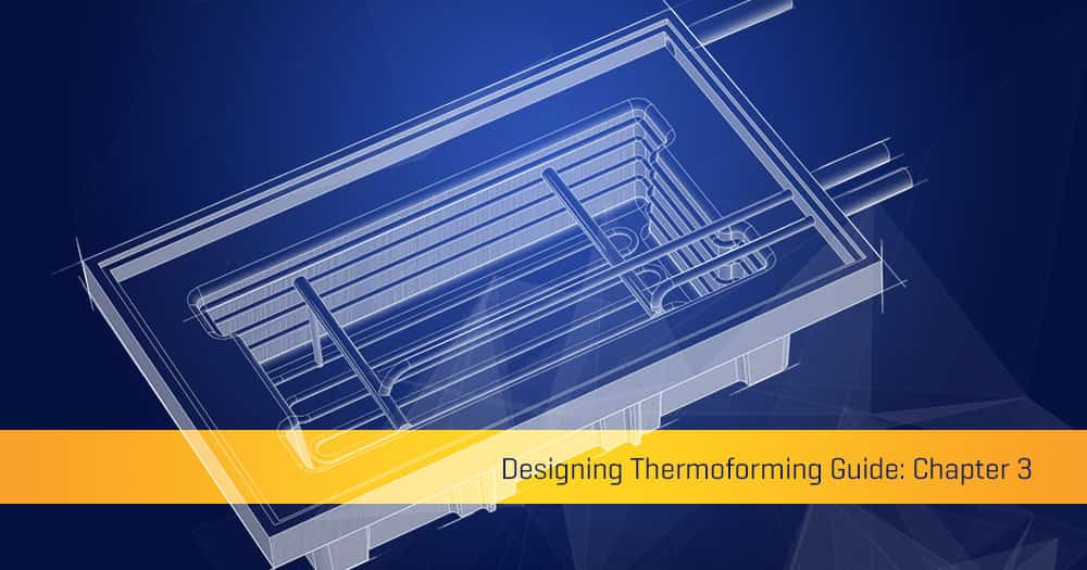
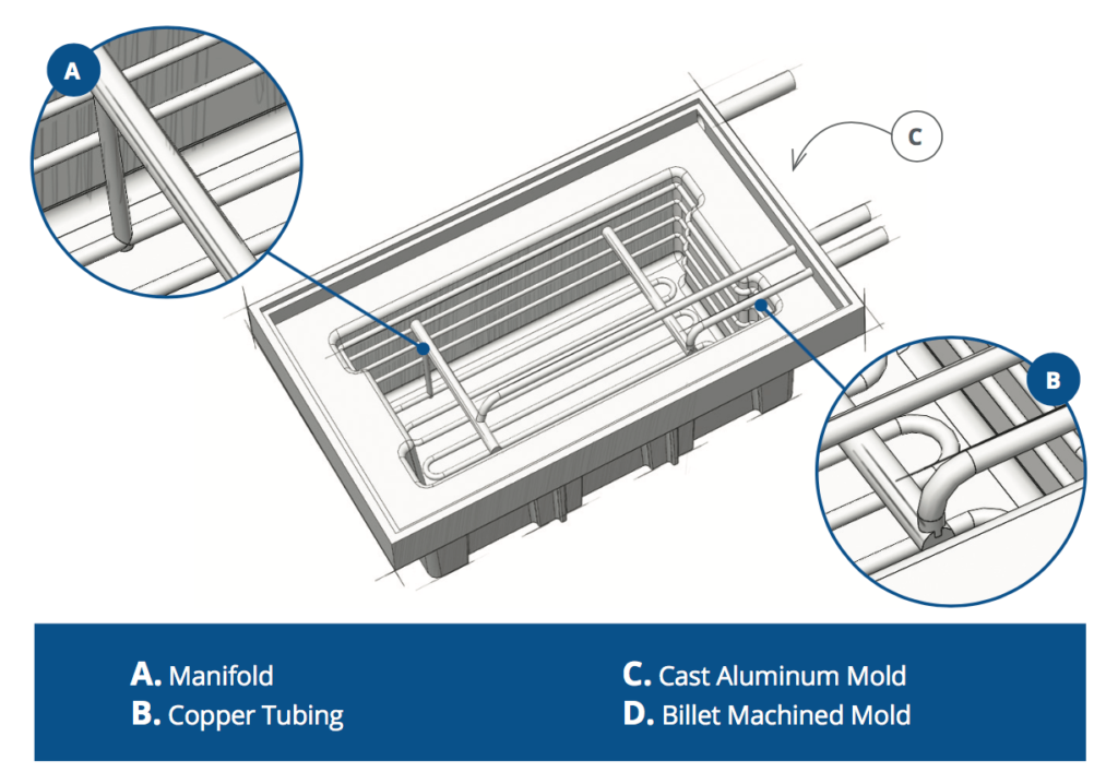
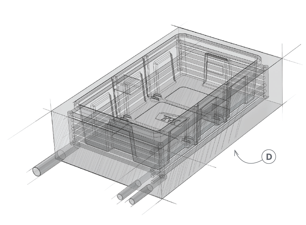
Anatomy of a Thermoforming Tool
Ray Products’ Thermoforming Tooling
- Billet Machined or Cast Aluminum
- Guaranteed for Life
- Pressure Forming up to 6 feet x 10 feet
- Vacuum Forming up to 10 feet x 18 feet
- Up to 90% Savings Over Injection Molding Tooling
- Temperature-Controlled Tooling
- Gun-Drilled Cooling Channels
- Automated Tooling With Actuating Slides for Undercuts and Features
The Importance of Temperature Control
It’s important that, during the pressure forming process, the tooling maintains a consistent temperature. Without cooling, the tool would heat up during the pressure forming process as it comes into contact with more and more sheets of heated plastic. This would require waiting for the tool to cool between the molding of each part, significantly slowing the manufacturing process.
Our liquid cooling system circulates liquid through the tool during the pressure forming process, drawing heat away from the mold and allowing the production run to move rapidly while maintaining the quality of the thermoformed parts.
The cooling channels are created during the tooling manufacture process, using a precision drilling technique called “gun drilling,” which was originally developed for (you guessed it) drilling out the barrels of precision firearms.
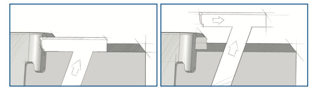
Tooling Automation
At Ray Products, we incorporate slides and moving cores into our pressure forming molds where necessary.
These allow the mold to shift after the plastic has been formed to let the finished part be removed without resistance from undercuts and negative draft angles. Traditionally, this is done manually, but at Ray Products we have a fully automated system that contracts the tooling when the formed part has been molded and is ready to be removed from the tool.
Releasing Undercuts
- Very small undercuts can sometimes be released from a normal tool.
- Most undercuts require a tool that slides to release the undercut.
- Luckily, Ray Products uses fully automated tooling to save time and reduce costs.
- In addition, our state-of-the-art forming equipment allows for perfect synchronization of cylinder and slide-driven tooling.
Tech Tip: If your undercut requires a moving section in the mold, you must allow for a parting or witness line on the part. On an inward-facing angle, the parting line is typically hidden at the point where the formed part turns in. On other undercuts, the parting line can be used as a transition between features and geometry or an area of delineation of texture and no texture.
Molded-In Textures
Thermoforming gives you two ways to create texture in your final part.
1. Pressure Forming
In pressure forming, texture is created by acid etching a pattern or texture onto the tool surface. By etching a texture, you can have smooth and textured areas on the same surface on the same part, making pressure-formed and injection-molded parts virtually identical aesthetically.
2. Vacuum Forming Textures
In vacuum forming, texture is created by using a pre-textured material and running the textured side of the material away from the mold surface, so the outside surface of the molded part has the sheet texture. Texture can be haircell, suede, matte or any other variation; it can also be high-gloss smooth.
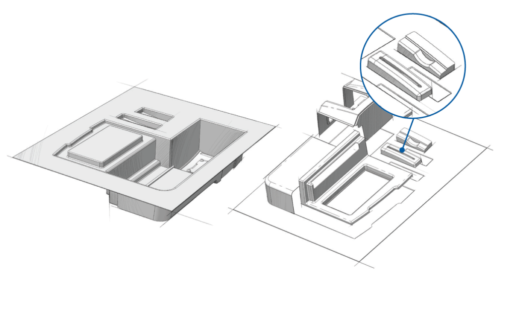
Combining Multiple Parts in a Single Mold
How It Works
- A single tool is designed to create several parts.
- During the trimming process, our six-axis robots separate each individual part.
Advantages
- Material costs are reduced by optimizing part layout.
- Tooling costs are reduced through consolidation.
- Overall manufacturing speed is increased.
Size Matters
Ray Products operates the largest pressure forming equipment on the West Coast, capable of pressure forming a full 6′ x 10′ and vacuum forming a full 10′ x 18′. That not only lets you thermoform larger single parts, but also consolidate more parts onto a single tool than ever before.
A Multi-Part Assembly