This is the second post in our series from our Thermoforming Handbook, a guide that, until now, was only available to our customers and partners. We’re releasing the whole thing in a series of posts right here on our blog. Chapter 1’s blog post is right here.
If you’re someone who uses custom plastic manufacturing professionally and you’re interested in getting your own copy, just send us a message and we’ll be happy to send you one. As always, these are general guidelines. Any project or design needs to be reviewed by a qualified thermoforming professional before it goes into production, and the sooner you get one of those qualified professionals involved in the process, the smoother things tend to go. If you’re looking for a qualified professional, we know a few who would be happy to help.
Welcome to Chapter 2 of our design guide, where we’ll learn some important design considerations when designing for thermoforming. We’ll cover draw ratios, sharp angles, undercuts, draft angles and more. Thermoforming is a very capable process, and the more you understand about its technical aspects, the more flexibility you’ll have in design.
Draw Ratios
A draw ratio is the calculation that lets you know what gauge of plastic you need to start with for any given thermoformed part.
The Importance of Stretching
Thermoforming works by stretching a sheet of plastic over a mold. The more stretching that occurs, the thinner the plastic gets.
You Want It Thick, but Not Too Thick
Using a draw ratio calculation, you can make sure you start with plastic that’s thick enough to give you the final thickness you need, but not so thick that you waste money on overly expensive materials.
Draw Ratio Formulas & Examples
The basic formula for a draw ratio is:
(Surface Area of the Part) / (Footprint of the Part) = Draw Ratio
Sample Draw Ratio Calculation
Let’s say a sample part was 48” x 36” by 12” deep.
Step 1: Calculate the Surface Area
2(48” x 12”) + 2(36” x 12”) + (48” x 36”)
1,152” + 864” + 1,728”
Surface Area = 3,744”
Step 2: Calculate the Footprint
48” x 36” = 1,728”
Step 3: Calculate the Draw Ratio
3,744” / 1,728” = 2.17
Calculate Starting Material Thickness
Once you have your draw ratio, you can use it to calculate your minimum starting gauge with the formula:
(Draw Ratio) x (Desired Finished Gauge) = (Minimum Starting Gauge)
Sample Starting Material Thickness Calculation
Using the draw ratio of 2.17 that we calculated in the last sample, let’s assume that our target final gauge is .150”. So – we’d simply calculate:
2.17 x .150” = 0.330”
All that math, and we’ve now learned that we need to start with a sheet of 0.330” gauge thermoplastic to make our part.
Or do we?
Rules Can Be Broken
Draw ratios aren’t an immutable rule of thermoforming; they’re just a starting point. The best way to make sure your design is going to work is to run it past an experienced thermoforming engineer.
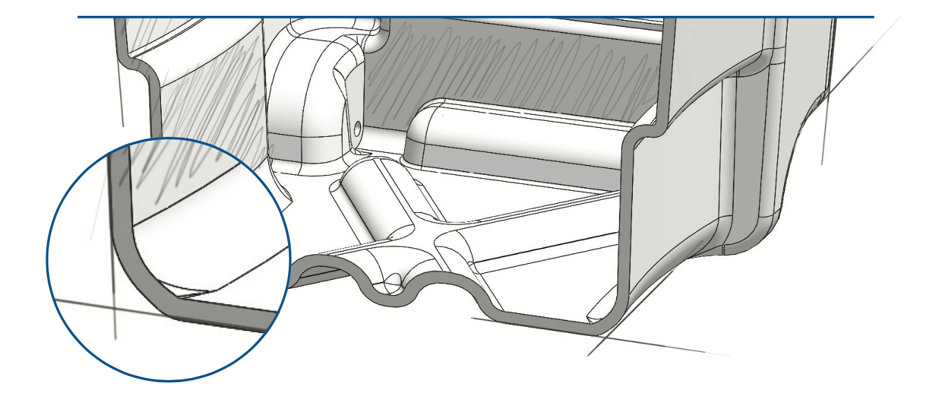
Sharp Angles in Thermoforming
Corners that are too sharp can result in weaknesses in the final part. But don’t worry, there are a number of techniques you can use to create strong corners. And, because we’re nice people, we’ll even show them to you!
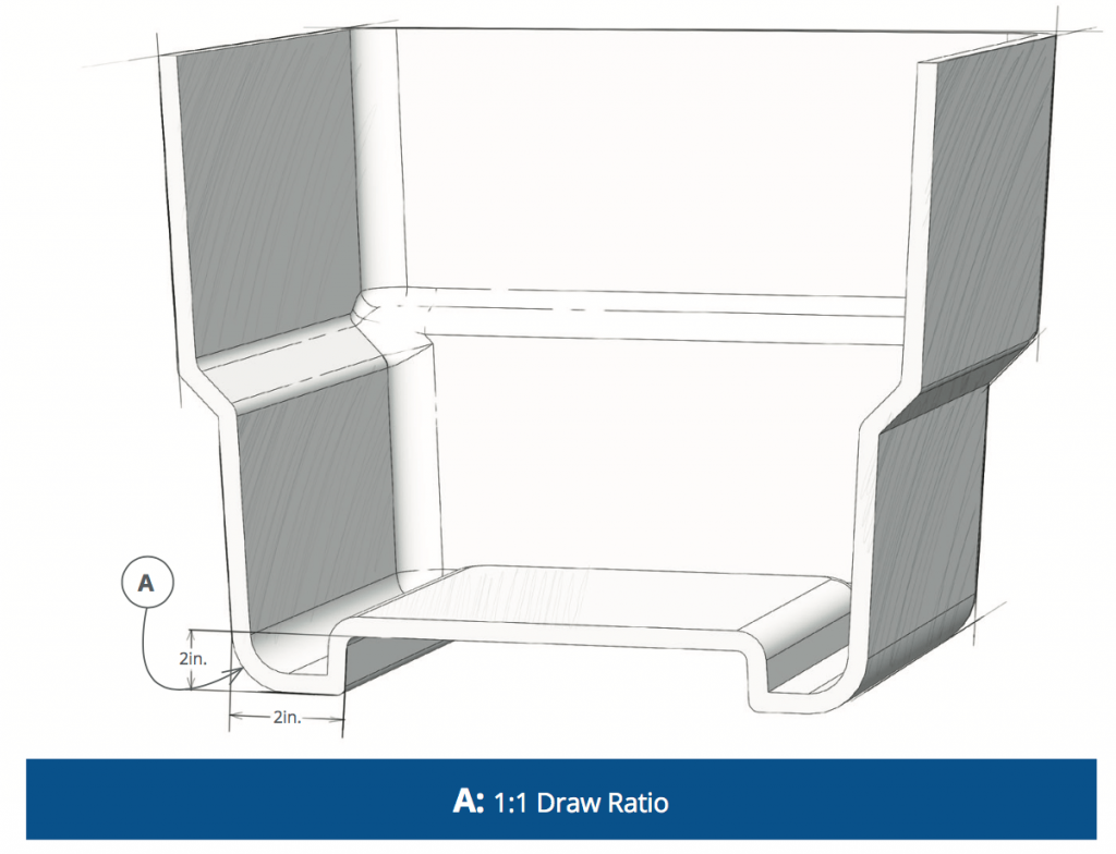
Use a Chamfer
Using the magic of geometry, a chamfer transforms one sharp corner into several less-sharp corners.
Bonus Tip #1: Every Material Is Different
When it comes to sharp angles, the material you use matters.
For example, ABS and PVC can handle much sharper corners than polyethylene and polycarbonate.
Bonus Tip #2: Pressure Forming Is Different From Thermoforming
Process matters, too. If you’re pressure forming, you can safely make significantly sharper corners than with vacuum forming. It’s one of the reasons that pressure forming is usually your best choice where aesthetics and multi-part assemblies are a top priority.
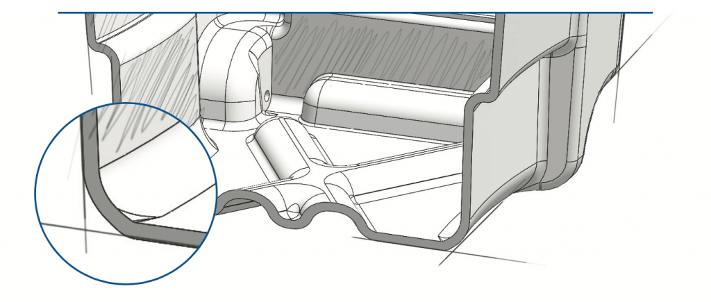
Add a Radius
This table is a good rule of thumb for just how large that radius should be.
| Depth of Part | Minimum Corner Radius | |
|---|---|---|
| A | 0" - 3" | .015” - .125” |
| B | 3” – 6” | .125” - .250” |
| C | 6” – 12” | .250”+ |
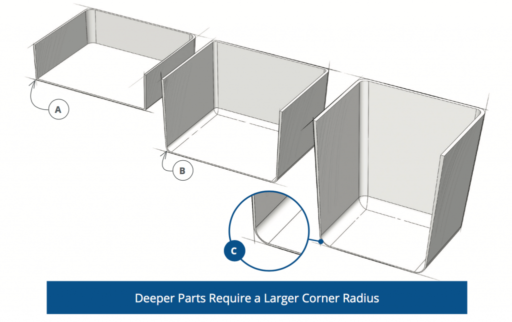
You can avoid a sharp three-sided corner by using a chamfer or radius. The radius at the bottom of the draw is most critical. The deeper the part, the larger the radius or chamfer required.
Undercuts & Draft Angles
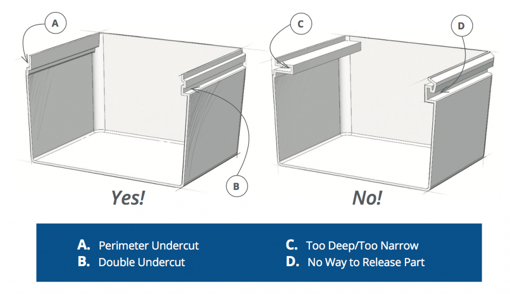
It’s important to understand undercuts in pressure forming design since they can add significant value to your overall product.
Typically, undercuts are an inward-facing flange, but they can include other features that are not parallel to the direction of pull out of the mold. Undercuts increase your tooling cost, but the cost increase is significantly less than if you were to incorporate the undercut into an injection molding or structural foam molding tool.
Benefits of Pressure Forming Undercuts
- Increase strength and rigidity
- Provide fastening points
- Hide trimmed edges
Unstuck Undercuts
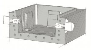 Small undercuts and the right material can sometimes allow the part to shrink away from the mold surface and be removed straight from the tool. Normal undercuts require movable section(s) of the mold.
Considerations for Designing Undercuts
- Don’t forget undercuts in draw ratio calculations.
- When two undercuts meet at a corner, step the undercut back into the corner to avoid thinning.
- Plan for the parting/witness line where the mold retracts.
- Don’t be afraid to ask. What cannot be done in other molding processes can often be achieved in pressure forming.
Draft Angles
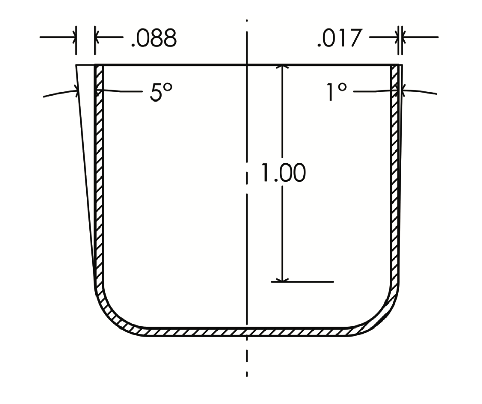 Industry Standard Draft Angles
- 1.5° to 2° for vertical drafts on female features
- 4° to 6° for vertical drafts on male features
- 0° and negative drafts are possible, but require special accommodation
Corrugated Ribs, Louvers & Vents
Ribs and louvers are a great design feature and are essential for many electronic enclosures.
Key Considerations
- Don’t forget the draw ratio.
- Too many ribs and louvers too close together can cause excessive thinning.
- Keep the distance between each rib and louver at least equal to its depth.